Smart Assistive Three-Jointed Robotic Arm
This project is a proof-of-concept three-jointed robotic arm inspired by assistive technology for people with limited mobility. I assembled and wired the arm, programmed four servo motors, developed an alternative laptop-based control system after identifying a faulty joystick, and added an ultrasonic distance sensor with a seven-segment display. The project taught me that engineering is not simply about following instructions; it involves testing individual systems, identifying failures, developing solutions, and adapting when the original plan does not work.
| Alice S. | Nord Anglia International School Dubai | Biomedical, Electrical, and Mechanical Engineering | Incoming Year 11 |
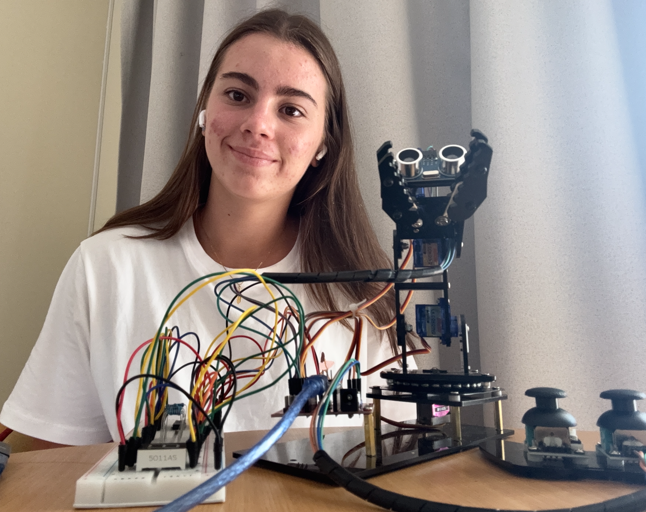
Final Milestone
For my final milestone, I completed two modifications to the original robotic-arm project. I added an HC-SR04 ultrasonic distance sensor and a single-digit seven-segment display. The sensor measures the distance between the claw and a nearby object, while the display shows the measured distance from zero to nine centimetres.
The seven-segment display is connected through a 74HC595 shift register. This integrated circuit simplified the breadboard wiring because it allowed the Arduino to control the display segments using only three digital pins.
A major challenge was combining the sensor and display code with the existing robotic-arm program without interfering with the servo motors or laptop controls. To solve this, I tested the sensor and display independently before integrating them with the main program one component at a time. This method allowed me to identify errors more efficiently and confirm that each subsystem worked correctly before moving forward.
My main triumph was successfully operating the arm controls, ultrasonic sensor, and seven-segment display together as one complete system. The final design uses one joystick to control the base and shoulder, while a Python interface on my laptop controls the elbow and claw. The ultrasonic sensor continuously measures distance, and the display presents the result while the arm is operating.
By the end of BlueStamp Engineering, I had assembled my first robot, wired and tested several electronic systems, programmed an Arduino, created a Python control interface, and learned how to troubleshoot both hardware and software problems systematically.
In the future, I would improve the cable management, replace the faulty joystick, make the arm’s movements smoother, and explore more advanced assistive features, such as automated movement routines or object recognition.
Second Milestone
For my second milestone, I completed and tested the main robotic-arm system. Four servo motors control the base rotation, shoulder, elbow, and claw. The original design used two joystick modules, with each joystick controlling two servo motors.
During testing, the elbow and claw motors began twitching and responding inconsistently. The main challenge was determining whether the problem came from the motors, wiring, Arduino signals, code, or joystick.
To isolate the issue, I swapped the motors between the two joystick circuits, checked the electrical connections, and compared how the motors responded. The motors connected to the working joystick operated correctly, while the motors connected to the other joystick began twitching. This confirmed that the motors and wiring were functioning correctly and that the second joystick had a physical fault.
Instead of allowing the faulty joystick to stop the project, I developed an alternative laptop-based control system. I created a Python interface in Thonny with buttons for controlling the elbow and claw. When a button is held, Python sends a movement command to the Arduino. When the button is released, Python sends a stop command.
My main triumph during this milestone was restoring reliable control of the complete robotic arm despite the hardware failure. The working joystick controlled the base and shoulder, while the laptop interface successfully controlled the elbow and claw.
Before my final milestone, I still needed to add the ultrasonic sensor and seven-segment display, combine their code with the robotic-arm program, and test the entire project as one integrated system.
First Milestone
For my first milestone, I assembled the physical structure of the three-jointed robotic arm and began connecting its mechanical and electrical systems.
The arm uses four servo motors. One servo rotates the base, one moves the shoulder, one moves the elbow, and one opens and closes the claw. Although the arm has three main joints, the claw requires an additional servo motor.
I connected the servo motors and joystick modules to an Arduino-compatible microcontroller. The Arduino reads the analogue values produced by the joysticks and converts those readings into changes in the servo angles.
One of my first challenges was correctly positioning the servo horns and preventing the motors from attempting to move beyond the arm’s physical limits. To solve this, I tested each servo separately and moved the motors to a neutral position of approximately 90 degrees before attaching or repositioning the servo horns.
This calibration process was an important early triumph because it allowed the mechanical structure to move more predictably and reduced the risk of damaging the servos or frame.
I also had to organise a large number of wires and understand how the mechanical components, electrical connections, and Arduino code worked together. By the end of the milestone, I had completed the physical base of the robot and established a working foundation for testing the full joystick-control system.
Circuit Schematic
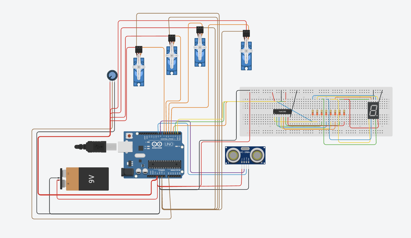
The completed system contains the following components:
- Four servo motors controlling the base, shoulder, elbow, and claw.
- One working joystick controlling the base and shoulder.
- An Arduino-compatible microcontroller.
- A Python laptop interface controlling the elbow and claw.
- An HC-SR04 ultrasonic distance sensor.
- A single-digit seven-segment display.
- A 74HC595 shift register.
- A breadboard, resistors, and jumper wires.
Main Pin Connections
| Component | Arduino Connection |
|---|---|
| Base servo | Digital pin D4 |
| Shoulder servo | Digital pin D5 |
| Elbow servo | Digital pin D6 |
| Claw servo | Digital pin D7 |
| Working joystick X-axis | Analogue pin A0 |
| Working joystick Y-axis | Analogue pin A1 |
| 74HC595 data pin | Digital pin D1 |
| 74HC595 latch pin | Digital pin D2 |
| 74HC595 clock pin | Digital pin D3 |
| Ultrasonic sensor trigger | Digital pin D8 |
| Ultrasonic sensor echo | Digital pin D9 |
| Ultrasonic sensor power | 5V and GND |
Code
My project uses two connected programs. The Arduino program controls the four servo motors, reads the working joystick, receives serial commands from the laptop, measures distance using the ultrasonic sensor, and updates the seven-segment display. The Python program creates the laptop interface used to control the elbow and claw after I identified a physical fault in the second joystick.
Arduino Control Code
Python Laptop Controller
The Python controller was run in Thonny. Holding a button sends a movement command to the Arduino, while releasing the button sends S to stop the movement.
The USB port listed in the Python program was the port assigned to the Arduino on my laptop. The port name may need to be changed if the program is run on another computer.
Bill of Materials
| Part | Note | Price | Link |
|---|---|---|---|
| Robot Arm Kit | Included the three-jointed robotic-arm frame, claw, Arduino-compatible microcontroller, four servo motors, two joystick modules, mounting components, screws, and the main wiring used to construct and control the arm. | $45.00 | Product Link |
| Electronics Kit | Included the breadboard, jumper wires, resistors, 74HC595 shift register, single-digit seven-segment display, and other circuit components used to create the display modification. | $14.00 | Product Link |
| 9V Barrel-Jack Cable | Used to connect the power source to the microcontroller. | $6.00 | Product Link |
| 9V Batteries | Used as a portable power source during testing. | $12.37 | Product Link |
| Precision Screwdriver Kit | Used to assemble and adjust the robotic-arm frame, servo horns, and mounting components. | $5.94 | Product Link |
| Digital Multimeter | Used to test voltage, continuity, and electrical connections while troubleshooting the circuit. | $11.00 | Product Link |
| HC-SR04 Ultrasonic Sensor | Purchased separately and used to measure the distance between the claw and nearby objects. | Not recorded | Not available |
Resources
- Cokoino CKK0006 Robot Arm GitHub Repository — Original base-project Arduino files, code, schematics, and setup materials.
- Cokoino Robot Arm for Arduino — Official product page for the robotic-arm kit used as the base of this project.
- Arduino Documentation — Reference material for Arduino programming, hardware, functions, and libraries.
- Python Tkinter Documentation — Reference material for creating the laptop control interface.
- PySerial Documentation — Reference material for serial communication between Python and the Arduino.
- BlueStamp Engineering Portfolio Template — Template used to structure and publish this portfolio.